Desert Online General Trading LLC
Dubai, United Arab Emirates
Desert Online General Trading LLC
Dubai, United Arab Emirates


🚀 Elevate your DIY projects with crisp visuals and seamless connectivity!
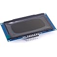
The Teyleten Robot 2.42-inch OLED LCD Display Module features a sharp 128x64 resolution powered by the SSD1309 driver IC. It offers flexible SPI or I2C serial interfaces configurable via onboard resistors, making it ideal for Arduino UNO R3 and similar single-board computers. Lightweight and compact, this white-light OLED module ensures easy integration and vibrant display performance for professional-grade electronics projects.
| Brand | Teyleten Robot |
| Manufacturer | Teyleten Robot |
| Product Dimensions | 7.12 x 4.35 x 1 cm; 24 g |
| Item part number | F105-1 |
| Ram Memory Technology | LPDDR3 |
| Operating System | Linux |
| Processor Brand | ARM |
| Processor Count | 1 |
| Compatible Devices | Single-board computers with I2C or SPI interfaces |
| Mounting Hardware | OLED display module |
| Number of items | 1 |
| Batteries Included | No |
| Batteries Required | No |
| Wireless Type | Bluetooth |
| Connector Type | I2C |
| Manufacturer | Teyleten Robot |
| Country of Origin | USA |
| Item Weight | 24 g |
Trustpilot
2 weeks ago
3 days ago