⏳ Build Your Time, One Solder at a Time!
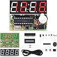
The MiOYOOW 4-Digit Digital Clock Kit is a DIY electronics project designed for students aged 13 and above. It features a user-friendly assembly process, accurate timekeeping, and dual alarm settings, making it an excellent educational tool for learning soldering and electronic principles.


| Brand | MiOYOOW |
| Color | 1 Pack-4 Digit Clock Kit(0.56 Inch) |
| Display Type | Digital |
| Style | 1 Pack-4 Digit Clock Kit(0.56 Inch) |
| Special Feature | Alarm |
| Product Dimensions | 2.6"W x 0.7"H |
| Power Source | DC |
| Age Range (Description) | over 13 years old |
| Room Type | Usb |
| Shape | Rectangular |
| Indoor/Outdoor Usage | Indoor |
| Theme | Science Fiction |
| Are Batteries Included | No |
| Item Weight | 0.05 Pounds |
| Alarm Clock | Yes |
| Watch Movement | Mechanical |
| Number of Items | 1 |
| Operation Mode | Mechanical |
| Manufacturer | WHDTS |
| Part Number | 1765 |
| Item Weight | 0.8 ounces |
| Item model number | 1765 |
| Is Discontinued By Manufacturer | No |
| Item Package Quantity | 1 |
| Number Of Pieces | 17 |
| Special Features | Alarm |
| Included Components | electronic cpmponents |
| Batteries Included? | No |
| Batteries Required? | No |
C**T
The best electronics kit on Amazon - make this in ten minutes! LEARN ELECTRONICS - here is how!
This is a great kit to learn about electronics. Of all the kits available on Amazon this one is most likely the best for learning. It also ends up with a great clock. I have built three of them so that for my day job I can track my employees who are in different time zones.If you are looking for a way to learn about electronics, a way to learn about soldering, a great alarm clock that you can be proud to have built – THIS is the kit to purchase. It is the best one on Amazon. Look no further!I am using this in my university courses to get students exposed to circuit components and construction.Here is a portion of my lab assignment for this project that might help you build it.ToolsMake sure you have a• Soldering Iron• Solder• Small wire clippers• Optional – a silicon work mat (so you wont burn the surface you are working on)Here are ways to make your project NOT work.• Inserting certain components with the wrong polarity (in the wrong direction).• Cold solder joints.• Missing a solder connection.• Solder bridges (inadvertently connecting two solder pads on the back of the PCB).• Not inserting the power barrel connector all the way in.Layout the parts in the order that they will be installed.Build• Insert the two resistors and bend the leads to hold the resistors in place. They can be placed in any direction as resistors do not have polarity.• Install the two 30 pf ceramic capacitors and bend the leads to hold the capacitors in place. Make sure you put the right capacitors in the right locations.• Install the 104 pf ceramic capacitor and bend the leads to hold the capacitor in place. Make sure you put the right capacitor in the right location.• Install the 12 MHz crystal oscillator and bend the leads to hold the oscillator in place.• Solder all the leads to the PCB board. Remember to heat the board and the wire and not the solder. The solder will flow when the PCB connection and wire are hot enough. The connection should be shiny if a good solder connection has been made.• Clip all the leads.• Install the network resistor. The network resistor must be installed with the dot aligned with the mark on the PCB board.• Solder the network resistor’s nine pins.• Insert the DIP-20 IC socket. The DIP-20 IC socket must be installed with the notch aligned with the printed notch on the PCB.• Solder the 20 pins.• Insert the transistor. The transistor must be installed with the flat side of the transistor aligned with the flat side printed on the PCB. Bend the leads to hold the transistor in place.• Solder the three leads.• Clip the three leads.• Insert the two button switches. If they aren’t going easily in they are most likely being installed incorrectly.• Solder the eight pins.• Install the 10 uF 25V electrolytic capacitor. Electrolytic capacitors have polarity. The shorter leg goes into the shaded area on the PCB. Bend the leads to hold it on place.• Solder the leads.• Clip the leads.• Install the power socket.• Solder the three pins. These pins are close. Make sure there aren’t any solder bridges.• Install the buzzer. The buzzer has polarity. Insert the longer lead into the hold marked with a + on the PCB.• Solder the leads.• Clip the leads.• Insert the 4-bit display. Make sure there isn’t any Styrofoam on the leads. The display has polarity. Make sure the decimal points are toward the other components. The pins might need slight adjustment to fit into the holes.• Solder the ten pins.• Clip the pins.• Insert the IC making sure that the notch in the chip are aligned with the notch on the socket. Check that the pins are aligned with the sockets before pressing the chip firmly in place.• Remove the white sticker from the buzzer for a louder sound – it’s really loud with it off.• Plug the power cord into USB power and then plug the barrel connector into the clock. The connection is firm and might not be fully in place. If the clock turns off when you take your hand off the power cords then it wasn’t fully inserted.Consider covering the back with tape – like blue painters’ tape – to prevent shorting out the clock. Remember too, there aren’t any memory components so when power is removed and then reapplied the clock will reset back to 12:59.All in all, this project can be completed in fifteen minutes or less!
J**H
Good Clock, Enjoyable Kit
As a kit:I would call this an easy to intermediate assembly.The silkscreen is very easy to understand, and pretty much explains everything you need to know to assemble the kit.If you have any questions about it, the manual is useful, but not a be-all end-all.A small amount of knowledge of how to read a silkscreen is necessary to enjoy the assembly process.I enjoyed the process.If you plan to carry it around, you might want to conformal coat the solder side.As a clock:Once you've built it, you'll have an hours:minutes:seconds 24 hour digital clock to enjoy.This thing has more features than many desk clocks, and is rather quite useful, even if the UI can be a little confusing.Fortunately the manual does adequately explain enough that you can figure out everything else via experimentation.There's a convenient connector on the front that provides low-current 5v signal when the alarm buzzer is active.The manual cautions against going above 12v input, however the 78L05 regulator on the input accepts up to 35v.I don't know why you would want to apply 35v to your clock, but you can.I use it on a 2S LiPo battery. You'll want a battery monitor if you use a higher cell count LiPo.Clock Mode>As you power up your kit, you'll be greeted by the Clock screen.HH:MM:SS, with seconds incrementing and the colons flashing at 1Hz. Buttons S1 and S2 don't do anything. S3 changes modes.Time appears accurate. It only deviated by about two seconds from my watch over the course of a full day. I would trust this as an accurate clock.Timeset mode>Press S3 to enter Time Set mode. You'll see the time from before, but now all six digits are flashing. Seconds continue incrementing. Use S1 to increment the minutes, and S2 to increment the hours.Alarm Set mode>S3 from timeset mode sets the alarm clock. You'll be presented with a time on the display, with the colons steady.Use S1 to increment the minutes, and S2 to increment the hours. Continue past 23 hours (11PM) so the display shows --:--:-- to disable the alarm clock outright.Countdown Timer>S3 from Alarm Set activates the countdown timer. It remembers the set-mode you last used, but not the time you set.This could display any number of 0's with no colons, and the buzzer may sound.Press S2 to cycle through the digits, and S1 to increment the selected digit. HH:MM:SS, maximum value 99:59:59. Cycle past the last digit to activate the count-down. S1 doesn't do anything during the countdown.Stopwatch>Cycle past the countdown to display 00:00:00. This is a simple stopwatch. MM:SS:1/100's. Maximum value 59:59:99, cycles around if it overflows.Press S2 to start and stop the timer. Press S1 to reset.Counter>Press S3 from Stopwatch to get a simple counter. 00 00 00 with no colons will appear on the display. Theoretical maximum value 999999, but I'm not patient enough to find out.Press S2 to increment. S1 to reset.
Trustpilot
1 day ago
2 days ago